
Bluetooth Controlled Door Lock/Unlock with EEPROM
- Ramesh G

- Apr 6, 2022
- 4 min read
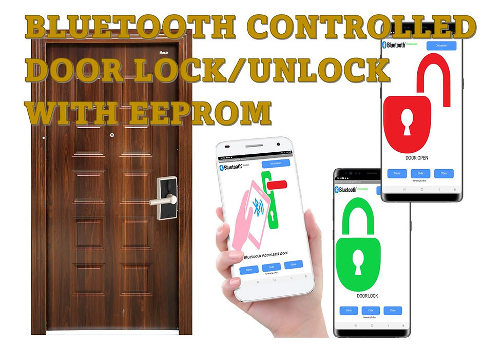
Here to learn How to Make an Bluetooth controlled Door Opening and closing System Using Arduino, LCD, servo, LED and android application. The Servo Motor to control door open and close through bluetooth using android application. The Red/Green (Bi colour) LED using for Door Lock/Unlock indication and LCD display 16x2 using for Door open/close status.
The Door locked/unlocked information number storing in Arduino EEPROM at every time of door Open/close. When the power of the Arduino the EEPROM remember the previously stored number and maintaining the door lock/unlock status.
Circuit Diagram
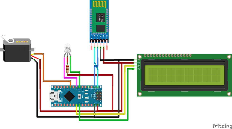
Components Required
Arduino Nano - 1 no
Bluetooth module HC-05 - 1no
Bi color LED (CA) - 1 no
Servo mini SG90 - 1 no
Servo motor
A servo motor is an electric device used for precise control of angular rotation. It is used in applications that demand precise control over motion, like in case of control of a robotic arm.
The rotation angle of the servo motor is controlled by applying a PWM signal to it.
By varying the width of the PWM signal, we can change the rotation angle and direction of the motor.
Wire Configuration:
Brown - Ground wire connected to the ground of system
Red - Powers the motor typically +5V is used
Orange - PWM signal is given in through this wire to drive the motor
Servo SG90 Data Sheet
Bluetooth HC-05 Module
HC-05 is a Bluetooth module which is designed for wireless communication. This module can be used in a master or slave configuration. Bluetooth serial modules allow all serial enabled devices to communicate with each other using Bluetooth.
It has 6 pins,
1.Key/EN: It is used to bring Bluetooth module in AT commands mode. If Key/EN pin is set to high, then this module will work in command mode. Otherwise by default it is in data mode. The default baud rate of HC-05 in command mode is 38400bps and 9600 in data mode.
HC-05 module has two modes,
Data mode: Exchange of data between devices.
Command mode: It uses AT commands which are used to change setting of HC-05. To send these commands to module serial (USART) port is used.
2. VCC: Connect 5 V or 3.3 V to this Pin.
3. GND: Ground Pin of module.
4. TXD: Transmit Serial data (wirelessly received data by Bluetooth module transmitted out serially on TXD pin)
5. RXD: Receive data serially (received data will be transmitted wirelessly by Bluetooth module).
6. State: It tells whether module is connected or not.
HC-05 module Information
HC-05 has red LED which indicates connection status, whether the Bluetooth is connected or not. Before connecting to HC-05 module this red LED blinks continuously in a periodic manner. When it gets connected to any other Bluetooth device, its blinking slows down to two seconds.
This module works on 3.3 V. We can connect 5V supply voltage as well since the module has on board 5 to 3.3 V regulator.
As HC-05 Bluetooth module has 3.3 V level for RX/TX and microcontroller can detect 3.3 V level, so, no need to shift transmit level of HC-05 module. But we need to shift the transmit voltage level from microcontroller to RX of HC-05 module.
HC-05 Default Settings
Default Bluetooth Name: “HC-05”
Default Password: 1234 or 0000
Default Communication: Slave
Default Mode: Data Mode
Data Mode Baud Rate: 9600, 8, N, 1
Command Mode Baud Rate: 38400, 8, N, 1
Default firmware: LINVOR
Download datasheet


Installing Library
To install the library navigate to the Sketch > Include Library > Manage Libraries… Wait for Library Manager to download libraries index and update list of installed libraries.
LiquidCrystal_I2C.h : you need to Download and install the LiquidCrystal_I2C library.
After installing the required libraries, copy the following code to your Arduino IDE.
Arduino Code
#include <Servo.h>
#include <EEPROM.h>
Servo myservo;
#include <LiquidCrystal_I2C.h>
LiquidCrystal_I2C lcd(0x27,16,2); // set the LCD address to 0x27 for a 16 chars and 2 line display
int RedLED = 4;
int GreenLED = 5;
void setup() {
Serial.begin(9600);
pinMode(RedLED, OUTPUT);
pinMode(GreenLED, OUTPUT);
pinMode(RedLED, HIGH);
pinMode(GreenLED, HIGH);
lcd.init(); // initialize the lcd
// Print a message to the LCD.
lcd.backlight();
// setup code here
myservo.attach(7);
if(EEPROM.read(0) == 1) // Reads the EEPROM value stored.
{
myservo.write(90); // Rotates the servo to 90 for lock
delay(200);
}
else if(EEPROM.read(0) == 2)// Reads the EEPROM value stored.
{
myservo.write(180); // Rotates the servo to 180 for open
delay(200);
}
lcd.setCursor(0,0);
lcd.print("BLUETOOTH ACCESS");
}
void loop() {
// put your main code here, to run repeatedly:
if(Serial.available() > 0)
{
char data;
data = Serial.read(); // The variable data is used to store the value sent by the Android app
switch(data)
{
case '1':
if(EEPROM.read(0) == 1)
{
EEPROM.write(0, 2); // Writes the number 2 to address 0 on the EEPROM.
Serial.println((EEPROM.read(0)));
for(int a = 90; a <= 180; a++) // Rotates the servo to the unlocked position
{
pinMode(RedLED, LOW);
pinMode(GreenLED, HIGH);
myservo.write(a);
delay(15);
lcd.setCursor(0,1);
lcd.print("DOOR OPEN ");
}
}
else if(EEPROM.read(0) == 2)
{
EEPROM.write(0, 1); // Writes the number 1 to address 0 on the EEPROM.
Serial.println((EEPROM.read(0)));
for(int x = 180; x >= 90; x--) // Rotates the servo to the locked position
{
pinMode(RedLED, HIGH);
pinMode(GreenLED, LOW);
myservo.write(x);
delay(15);
lcd.setCursor(0,1);
lcd.print("DOOR CLOSED");
}
}
break;
}
}
}
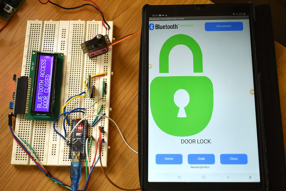
Demo:
Android application
First open Mobile application and select Bluetooth image button, after that select Bluetooth HC-05 device to connect and enter Password as mentioned above (0000 or 1234).


Hats off to the experts from Charlotte Locksmith company for a flawless installation of Bluetooth-controlled locks. They were punctual, courteous, and knew their stuff. The added benefit of being able to grant access to specific individuals remotely is a significant advantage.