
IoT Based Object Angle measure using MPU 6050 and Blynk
- Ramesh G

- May 24, 2021
- 5 min read
Updated: Jul 2, 2021

In this tutorial, Measuring the angle (Object Position) using MPU6050 sensor and connect with Blynk IoT cloud Platform.The MPU6050 sensor module has a built-in gyroscope and an accelerometer sensor. The gyroscope is used to determine the orientation and the accelerometer provides information about the angle, such as X, Y, and Z-axis data.
Circuit diagram

Components Required
LCD 20X4 line I2C - 1 no
ESP8266 12e- NodeMCU - 1 no
MPU6050 Accelerometer - 1 no

MPU6050 Sensor
MPU6050 sensor module is complete 6-axis Motion Tracking Device. It combines 3-axis Gyroscope, 3-axis Accelerometer and Digital Motion Processor all in small package. Also, it has additional feature of on-chip Temperature sensor. It has I2C bus interface to communicate with the microcontrollers. A micro-electro-mechanical system (MEMS) is used to measure velocity, acceleration, orientation, displacement, and many other motion-related parameters.
The MPU6050 module comes with an I2C and auxiliary I2C interfaces. The SCL and SDA pins of the MPU6050 are connected to the D1 and D2 pins of the NodeMCU, while the VCC and GND pins of the MPU6050 are connected to the 3.3V and Ground pin of NodeMCU.
3-Axis Gyroscope
The MPU6050 consist of 3-axis Gyroscope with Micro Electro Mechanical System(MEMS) technology. It is used to detect rotational velocity along the X, Y, Z axes as shown in below figure

When the gyros are rotated about any of the sense axes, the Coriolis Effect causes a vibration that is detected by a MEM inside MPU6050.
The resulting signal is amplified, demodulated, and filtered to produce a voltage that is proportional to the angular rate.
This voltage is digitized using 16-bit ADC to sample each axis.
The full-scale range of output are +/- 250, +/- 500, +/- 1000, +/- 2000.
It measures the angular velocity along each axis in degree per second unit.
3-Axis Accelerometer
The MPU6050 consist 3-axis Accelerometer with Micro Electro Mechanical (MEMs) technology. It used to detect angle of tilt or inclination along the X, Y and Z axes as shown in below figure

Acceleration along the axes deflects the movable mass.
This displacement of moving plate (mass) unbalances the differential capacitor which results in sensor output. Output amplitude is proportional to acceleration.
16-bit ADC is used to get digitized output.
The full-scale range of acceleration are +/- 2g, +/- 4g, +/- 8g, +/- 16g.
It measured in g (gravity force) unit.
When device placed on flat surface it will measure 0g on X and Y axis and +1g on Z axis.
DMP (Digital Motion Processor)
The embedded Digital Motion Processor (DMP) is used to compute motion processing algorithms. It takes data from gyroscope, accelerometer and additional 3rd party sensor such as magnetometer and processes the data. It provides motion data like roll, pitch, yaw angles, landscape and portrait sense etc. It minimizes the processes of host in computing motion data. The resulting data can be read from DMP registers.
On-chip Temperature Sensor
On-chip temperature sensor output is digitized using ADC. The reading from temperature sensor can be read from sensor data register.
The MPU-6050 module has 8 pins,
INT: Interrupt digital output pin.
AD0: I2C Slave Address LSB pin. This is 0th bit in 7-bit slave address of device. If connected to VCC then it is read as logic one and slave address changes.
XCL: Auxiliary Serial Clock pin. This pin is used to connect other I2C interface enabled sensors SCL pin to MPU-6050.
XDA: Auxiliary Serial Data pin. This pin is used to connect other I2C interface enabled sensors SDA pin to MPU-6050.
SCL: Serial Clock pin. Connect this pin to microcontrollers SCL pin.
SDA: Serial Data pin. Connect this pin to microcontrollers SDA pin.
GND: Ground pin. Connect this pin to ground connection.
VCC: Power supply pin. Connect this pin to +5V DC supply.
MPU-6050 module has Slave address (When AD0 = 0, i.e. it is not connected to Vcc) as,
Slave Write address(SLA+W): 0xD0
Slave Read address(SLA+R): 0xD1
MPU-6050 has various registers to control and configure its mode of operation. So, kindly go through MPU-6050 datasheet and MPU-6050 Register Map.
Calculations
Note that gyroscope and accelerometer sensor data of MPU6050 module consists of 16-bit raw data in 2’s complement form.
Temperature sensor data of MPU6050 module consists of 16-bit data (not in 2’s complement form).
Now suppose we have selected,
- Accelerometer full scale range of +/- 2g with Sensitivity Scale Factor of 16,384 LSB(Count)/g.
- Gyroscope full scale range of +/- 250 °/s with Sensitivity Scale Factor of 131 LSB (Count)/°/s.
then,
To get sensor raw data, we need to first perform 2’s complement on sensor data of Accelerometer and gyroscope.
After getting sensor raw data we can calculate acceleration and angular velocity by dividing sensor raw data with their sensitivity scale factor as follows,

Accelerometer values in g (g force)
Acceleration along the X axis = (Accelerometer X axis raw data/16384) g.
Acceleration along the Y axis = (Accelerometer Y axis raw data/16384) g.
Acceleration along the Z axis = (Accelerometer Z axis raw data/16384) g.
Gyroscope values in °/s (degree per second)
Angular velocity along the X axis = (Gyroscope X axis raw data/131) °/s.
Angular velocity along the Y axis = (Gyroscope Y axis raw data/131) °/s.
Angular velocity along the Z axis = (Gyroscope Z axis raw data/131) °/s.
Temperature value in °/c (degree per Celsius)
Temperature in degrees C = ((temperature sensor data)/340 + 36.53) °/c.
For example,
Suppose, after 2’ complement we get accelerometer X axes raw value = +15454
Then Ax = +15454/16384 = 0.94 g.
Blynk App
Is an IoT platform to connect your devices to the cloud, design apps to control them, analyze telemetry data, and manage your deployed products at scale
Blynk IoT Setup:


First of all, open the blynk application.
Click on the create a new project
Click on Choice Tools and select NodeMCU ESP8266.
Make sure the connection type is set to WIFI.
Watch video for further setup.
Installing Library
Download these libraries from the given links.
Blynk Download - Blynk Library can connect any hardware over Ethernet, WiFi, or GSM, 2G, 3G, LTE, etc.
Liquid Crystal Download
After downloading the .zip files, add the libraries in Arduino IDE by clicking on
To install the library navigate to the Sketch > Include Library > Manage Libraries… Wait for Library Manager to download libraries index and update list of installed libraries.
Subscribe and download code.
Subscribe and Download code.
Arduino Code
#include<Wire.h>
#include <SPI.h>
#define BLYNK_PRINT Serial
#include <Blynk.h>
#include <ESP8266WiFi.h>
#include <BlynkSimpleEsp8266.h>
#include <LiquidCrystal_I2C.h>
LiquidCrystal_I2C lcd(0x27,20,4); // set the LCD address to 0x27 for a 16 chars and 2 line display
char auth[] = "xxxxxx"; // You should get Auth Token in the Blynk App new project from NODEMCU
// WiFi network Credentials
const char* ssid = "xxxxx"; // your SSID
const char* password = "xxxx"; //your WIFI Password
const int MPU_addr=0x68;
int16_t AcX,AcY,AcZ,Tmp,GyX,GyY,GyZ;
int minVal=265;
int maxVal=402;
double x;
double y;
double z;
void setup(){
Wire.begin();
Wire.beginTransmission(MPU_addr);
Wire.write(0x6B);
Wire.write(0);
Wire.endTransmission(true);
Serial.begin(9600);
Blynk.begin(auth, ssid, password);
lcd.init(); // initialize the lcd
// Print a message to the LCD.
lcd.backlight();
}
void loop(){
Blynk.run();
Wire.beginTransmission(MPU_addr);
Wire.write(0x3B);
Wire.endTransmission(false);
Wire.requestFrom(MPU_addr,14,true);
AcX=Wire.read()<<8|Wire.read();
AcY=Wire.read()<<8|Wire.read();
AcZ=Wire.read()<<8|Wire.read();
int xAng = map(AcX,minVal,maxVal,-90,90);
int yAng = map(AcY,minVal,maxVal,-90,90);
int zAng = map(AcZ,minVal,maxVal,-90,90);
x= RAD_TO_DEG * (atan2(-yAng, -zAng)+PI);
y= RAD_TO_DEG * (atan2(-xAng, -zAng)+PI);
z= RAD_TO_DEG * (atan2(-yAng, -xAng)+PI);
Serial.print("AngleX= ");
Serial.println(x);
Serial.print("AngleY= ");
Serial.println(y);
Serial.print("AngleZ= ");
Serial.println(z);
Serial.println(" ***************");
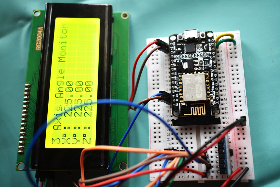
lcd.setCursor(0,0);
lcd.print("3 Axis Angle Monitor");
lcd.setCursor(0,1);
lcd.print("X");
lcd.print((char)223);
lcd.print(": ");
lcd.print(x);
lcd.setCursor(0,2);
lcd.print("Y");
lcd.print((char)223);
lcd.print(": ");
lcd.print(y);
lcd.setCursor(0,3);
lcd.print("Z");
lcd.print((char)223);
lcd.print(": ");
lcd.print(z);
Blynk.virtualWrite(V1, x);
Blynk.virtualWrite(V2, y);
Blynk.virtualWrite(V3, z);
delay(1000);
}
Then, upload the code to your NodeMCU board. Make sure you have selected the right board and COM port. Also, make sure you’ve inserted your WiFi Credentials in the code.
After a successful upload, open the Serial Monitor at a baud rate of 9600.


Comments