
nRF24L01 Wireless Temperature Monitor with Bluetooth
- Ramesh G

- Jan 2, 2022
- 6 min read

In this tutorial, we will learn how to make Radio Frequency wireless communication using the nRF24L01+PA transceiver module that operates on 2.4 - 2.5 GHz (ISM band) with range 1000m distance. An arduino based wireless communication and interface DHT 11 temperature Monitor.
The transmitter circuit side consists of an Arduino Nano, nRF24L01+PA module and DHT11 Temperature sensor. Arduino gets data from the DHT11 sensor and sends it to the nRF24L01 Transmitter. Then the nRF transmitter circuit transmits the data into the air.
The receiver circuit side consists of an Arduino Nano, nRF24L01+PA module, 1602 LCD with I2C module and Bluetooth HC-05. The nRF module receives the data from the transmitter and sends it to Arduino. An arduino send data to Bluetooth.
Components required
Transmitter:
Arduino Nano - 1 no
DHT 11 - 1 no
nRF24L01+PA- 1no

Receiver:
Arduino Nano - 1 no
Bluetooth HC-05 - 1 no
LCD1602 with I²C - 1no
nRF24L01+PA- 1no

Circuit diagram
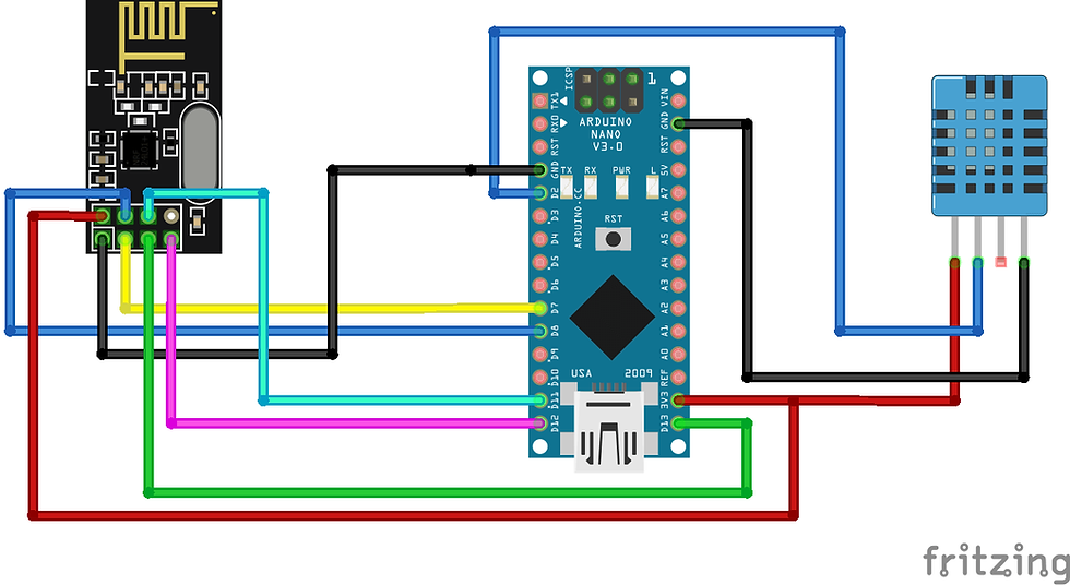
Transmitter Circuit:
Receiver Circuit:

NRF24L01 Wireless RF Module
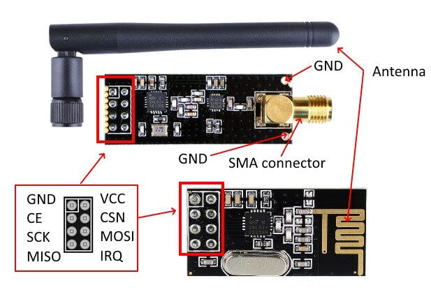
The NRF24L01 module is the latest in RF modules. This module uses the 2.4GHz transceiver from Nordic Semiconductor, the NRF24L01+. This transceiver IC operates in the 2.4GHz band and has many new features! Take all the coolness of the 2.4GHz NRF24L01+PA+LNA SMA Wireless Transceiver Antenna and add some extra pipelines, buffers, and an auto-retransmit feature.
This board features a reverse polarized SMA connector for maximum RF range. And there is PA and LNA circuit on board, with the external antenna it can reach long distance than the one without these parts.
This module comes with the 2.4G antenna (2DB), with a 250Kbps transmission rate on open-air it can reach the 800-1K meters communication distance.

Circuit Diagram for nRF24L01 PA

You can easily add it with your own MCU/ARM/PIC/AVR/STM32 system! What’s more, this nRF24L01+ module is designed with the Power amplifier and SMA antenna This allowed you to use the wireless communication up to 1000 meters! (No barrier)
Features :
It uses 2.4GHz global open ISM band, with license-free.
Transmit power is greater than +20 dBm.
Support six-channel data reception.
2Mbit/s speed makes high-quality VoIP possible
Multi-frequency points: 125 frequency points meet the needs of multi-point communications and frequency hopping.
Low cost: integrated with high-speed signal processing parts associated with RF protocol, such as: automatically re-send lost packets and generate acknowledge signal;
SPI interface facilitates the communication with MCU I/O port.
Facilitate the development for customers, without development RF part.
Software programming is fully compatible with NRF24L01 modules.
The PA stands for Power Amplifier. It merely boosts the power of the signal being transmitted from the nRF24L01+ chip. Whereas, LNA stands for Low-Noise Amplifier. The function of the LNA is to take the extremely weak and uncertain signal from the antenna (usually on the order of microvolts or under -100 dBm) and amplify it to a more useful level (usually about 0.5 to 1V)
The low-noise amplifier (LNA) of the receive path and the power amplifier (PA) of the transmit path connect to the antenna via a duplexer, which separates the two signals and prevents the relatively powerful PA output from overloading the sensitive LNA input.
RF Channel Frequency

The nRF24L01+ transceiver module transmits and receives data on a certain frequency called Channel. Also in order for two or more transceiver modules to communicate with each other, they need to be on the same channel. This channel could be any frequency in the 2.4 GHz ISM band or to be more precise, it could be between 2.400 to 2.525 GHz (2400 to 2525 MHz).
Each channel occupies a bandwidth of less than 1MHz. This gives us 125 possible channels with 1MHz spacing. So, the module can use 125 different channels which give a possibility to have a network of 125 independently working modems in one place.
ie The channel occupies a bandwidth of less than 1MHz at 250kbps and 1Mbps air data rate. However at 2Mbps air data rate, 2MHz bandwidth is occupied (wider than the resolution of RF channel frequency setting). So, to ensure non-overlapping channels and reduce cross-talk in 2Mbps mode, you need to keep 2MHz spacing between two channels.
nRF24L01+ Multiceiver Network

The nRF24L01+ provides a feature called Multiceiver. It’s an abbreviation for Multiple Transmitters Single Receiver. In which each RF channel is logically divided into 6 parallel data channels called Data Pipes. In other words, a data pipe is a logical channel in the physical RF Channel. Each data pipe has its own physical address (Data Pipe Address) and can be configured. The primary receiver acting as a hub receiver collecting information from 6 different transmitter nodes simultaneously. The hub receiver can stop listening any time and acts as a transmitter. But this can only be done one pipe/node at a time.
Arduino Nano
We have a complete understanding of how nRF24L01+ transceiver module works, we can begin hooking it up to our Arduino Nano
Connect VCC pin on the module to 3.3V on the Arduino and GND pin to ground. The pins CSN and CE can be connected to any digital pin on the Arduino. In our case, it’s connected to digital pin#7 and #8 respectively. Now we are remaining with the pins that are used for SPI communication.

As nRF24L01+ transceiver module require a lot of data transfer, they will give the best performance when connected up to the hardware SPI pins on a microcontroller. The hardware SPI pins are much faster than ‘bit-banging’ the interface code using another set of pins.
Note that each Arduino Board has different SPI pins which should be connected accordingly. For Arduino boards such as the UNO/Nano V3.0 those pins are digital 13 (SCK), 12 (MISO) and 11 (MOSI).
Installing Library
To install the library navigate to the Sketch > Include Library > Manage Libraries… Wait for Library Manager to download libraries index and update list of installed libraries.
DHT11: you need to Download and install the DHT11 library.
Adafruit Unified Sensor Download and install the sensor library.
Adafruit BusIO Download and install the signal library.
NRF24L01: you need to Download and install the RF library.
After installing the required libraries, copy the following code to your Arduino IDE.
Arduino Code
Transmitter Code
#include <SPI.h>
#include <nRF24L01.h>
#include <RF24.h>
#include "DHT.h"
const byte address[6] = "00001";
#define DHTPIN 2
#define DHTTYPE DHT11
DHT dht(DHTPIN, DHTTYPE);
RF24 radio(7, 8); // CN and CSN pins of nrf
struct MyData {
byte h;
byte t;
};
MyData data;
void setup()
{
Serial.begin(9600);
dht.begin();
radio.begin();
radio.setAutoAck(false);
radio.setDataRate(RF24_250KBPS);
radio.openWritingPipe(address);
radio.setPALevel(RF24_PA_MIN);
radio.stopListening();
}
void loop()
{
data.h = dht.readHumidity();
data.t = dht.readTemperature();
if (isnan(data.h) || isnan(data.t)){
Serial.println(F("Failed to read from DHT sensor!"));
return;
}
Serial.print("Humidity: ");
Serial.print(data.h);
Serial.print("Temperature: ");
Serial.print(data.t);
radio.write(&data, sizeof(MyData));
delay(1000);
}
Receiver Code
#include <SPI.h>
#include <nRF24L01.h>
#include <RF24.h>
#include <Wire.h>
#include <LiquidCrystal_I2C.h>
LiquidCrystal_I2C lcd(0x27,16,2); // set the LCD address to 0x27 for a 16 chars and 2 line display
const byte address[6] = "00001";
RF24 radio(7, 8); // CN and CSN pins of nrf
struct MyData {
byte h;
byte t;
};
MyData data;
void setup()
{
Serial.begin(9600);
radio.begin();
lcd.init(); // initialize the lcd
// Print a message to the LCD.
lcd.backlight();
radio.setAutoAck(false);
radio.setDataRate(RF24_250KBPS);
radio.openReadingPipe(0, address);
radio.setPALevel(RF24_PA_MIN);
radio.startListening();
//lcd.println("Receiver ");
}
void ReceiveData()
{
if ( radio.available() ) {
radio.read(&data, sizeof(MyData));
}
}
void loop()
{
ReceiveData();
// Serial.print("Humidity: ");
lcd.setCursor(0,0);
lcd.print("HUMIDITY:");
lcd.print(data.h);
lcd.print("%");
lcd.setCursor(0,1);
//Serial.print("Temperature: ");
// Serial.print(\n);
lcd.print("TEMPERATURE:");
lcd.print(data.t);
lcd.print((char)223);
lcd.print("C");
Serial.print(data.h);
Serial.print(":");
Serial.print(data.t);
Serial.print("\n");
delay(5000);
}
Amcharts
Here to used amChart Gauge for Temperature and Humididty data visualization.
Refer below demo HTML code for Gauges.
</style>
<script src="https://cdn.amcharts.com/lib/4/core.js"></script>
<script src="https://cdn.amcharts.com/lib/4/charts.js"></script>
<script src="https://cdn.amcharts.com/lib/4/themes/dark.js"></script>
<script src="https://cdn.amcharts.com/lib/4/themes/animated.js"></script>
<!-- Chart code -->
<script>
am4core.ready(function() {
// Themes begin
am4core.useTheme(am4themes_dark);
am4core.useTheme(am4themes_animated);
// Themes end
// create chart
var chart = am4core.create("chartdiv", am4charts.GaugeChart);
chart.hiddenState.properties.opacity = 0;
var axis = chart.xAxes.push(new am4charts.ValueAxis());
axis.min = 0;
axis.max = 160;
axis.strictMinMax = true;
axis.renderer.inside = true;
//axis.renderer.ticks.template.inside = true;
//axis.stroke = chart.colors.getIndex(3);
axis.renderer.radius = am4core.percent(97);
//axis.renderer.radius = 80;
axis.renderer.line.strokeOpacity = 1;
axis.renderer.line.strokeWidth = 5;
axis.renderer.line.stroke = chart.colors.getIndex(0);
axis.renderer.ticks.template.disabled = false
axis.renderer.ticks.template.stroke = chart.colors.getIndex(0);
axis.renderer.labels.template.radius = 35;
axis.renderer.ticks.template.strokeOpacity = 1;
axis.renderer.grid.template.disabled = true;
axis.renderer.ticks.template.length = 10;
axis.hiddenState.properties.opacity = 1;
axis.hiddenState.properties.visible = true;
axis.setStateOnChildren = true;
axis.renderer.hiddenState.properties.endAngle = 180;
var axis2 = chart.xAxes.push(new am4charts.ValueAxis());
axis2.min = 0;
axis2.max = 240;
axis2.strictMinMax = true;
axis2.renderer.line.strokeOpacity = 1;
axis2.renderer.line.strokeWidth = 5;
axis2.renderer.line.stroke = chart.colors.getIndex(3);
axis2.renderer.ticks.template.stroke = chart.colors.getIndex(3);
axis2.renderer.ticks.template.disabled = false
axis2.renderer.ticks.template.strokeOpacity = 1;
axis2.renderer.grid.template.disabled = true;
axis2.renderer.ticks.template.length = 10;
axis2.hiddenState.properties.opacity = 1;
axis2.hiddenState.properties.visible = true;
axis2.setStateOnChildren = true;
axis2.renderer.hiddenState.properties.endAngle = 180;
var hand = chart.hands.push(new am4charts.ClockHand());
hand.fill = axis.renderer.line.stroke;
hand.stroke = axis.renderer.line.stroke;
hand.axis = axis;
hand.pin.radius = 14;
hand.startWidth = 10;
var hand2 = chart.hands.push(new am4charts.ClockHand());
hand2.fill = axis2.renderer.line.stroke;
hand2.stroke = axis2.renderer.line.stroke;
hand2.axis = axis2;
hand2.pin.radius = 10;
hand2.startWidth = 10;
setInterval(function() {
hand.showValue(Math.random() * 160, 1000, am4core.ease.cubicOut);
label.text = Math.round(hand.value).toString();
hand2.showValue(Math.random() * 160, 1000, am4core.ease.cubicOut);
label2.text = Math.round(hand2.value).toString();
}, 2000);
var legend = new am4charts.Legend();
legend.isMeasured = false;
legend.y = am4core.percent(100);
legend.verticalCenter = "bottom";
legend.parent = chart.chartContainer;
legend.data = [{
"name": "Measurement #1",
"fill": chart.colors.getIndex(0)
}, {
"name": "Measurement #2",
"fill": chart.colors.getIndex(3)
}];
legend.itemContainers.template.events.on("hit", function(ev) {
var index = ev.target.dataItem.index;
if (!ev.target.isActive) {
chart.hands.getIndex(index).hide();
chart.xAxes.getIndex(index).hide();
labelList.getIndex(index).hide();
}
else {
chart.hands.getIndex(index).show();
chart.xAxes.getIndex(index).show();
labelList.getIndex(index).show();
}
});
var labelList = new am4core.ListTemplate(new am4core.Label());
labelList.template.isMeasured = false;
labelList.template.background.strokeWidth = 2;
labelList.template.fontSize = 25;
labelList.template.padding(10, 20, 10, 20);
labelList.template.y = am4core.percent(50);
labelList.template.horizontalCenter = "middle";
var label = labelList.create();
label.parent = chart.chartContainer;
label.x = am4core.percent(40);
label.background.stroke = chart.colors.getIndex(0);
label.fill = chart.colors.getIndex(0);
label.text = "0";
var label2 = labelList.create();
label2.parent = chart.chartContainer;
label2.x = am4core.percent(60);
label2.background.stroke = chart.colors.getIndex(3);
label2.fill = chart.colors.getIndex(3);
label2.text = "0";
}); // end am4core.ready()
</script>
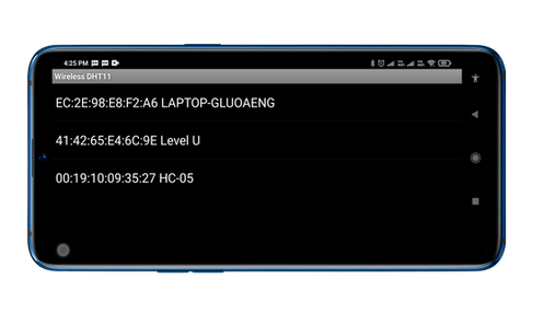
Android application
First open Mobile application and select Bluetooth image button, after that select Bluetooth HC-05 device to connect and enter Password as mentioned above (0000 or 1234).


Subscribe and Android App


Comments