
GPS Coordinates and GPS Clock
- Ramesh G

- Apr 11, 2022
- 4 min read
In this project, we have shown how to interface a GPS neo6M module with Arduino nano, 20x4 LCD display. GPS (global positioning system) coordinates are usually expressed as the combination of latitude and longitude. The GPS coordinates data for longitude, latitude and GPS clock is displayed on the LCD.
GPS Coordinates
GPS coordinates are formed by two components that are a latitude , giving the north-south position, and a longitude, giving the east-west position. Use this map to convert any address in its GPS coordinates. You can also find the location of any GPS coordinates, and geocode its address if available.
clock-Time
Local time is the date/time reported by your PC (as seen by your web browser). If your PC clock is accurate to a second then the other time scales displayed above will also be accurate to within one second.
UTC, Coordinated Universal Time, popularly known as GMT (Greenwich Mean Time), or Zulu time. Local time differs from UTC by the number of hours of your timezone.
GPS clock, Global Positioning System time, is the atomic time scale implemented by the atomic clocks in the GPS ground control stations and the GPS satellites themselves. GPS time was zero at 0h 6-Jan-1980 and since it is not perturbed by leap seconds GPS is now ahead of UTC by 18 seconds.
Loran-C, Long Range Navigation time, is an atomic time scale implemented by the atomic clocks in Loran-C chain transmitter sites. Loran time was zero at 0h 1-Jan-1958 and since it is not perturbed by leap seconds it is now ahead of UTC by 27 seconds.
TAI, Temps Atomique International, is the international atomic time scale based on a continuous counting of the SI second. TAI is currently ahead of UTC by 37 seconds. TAI is always ahead of GPS by 19 seconds.
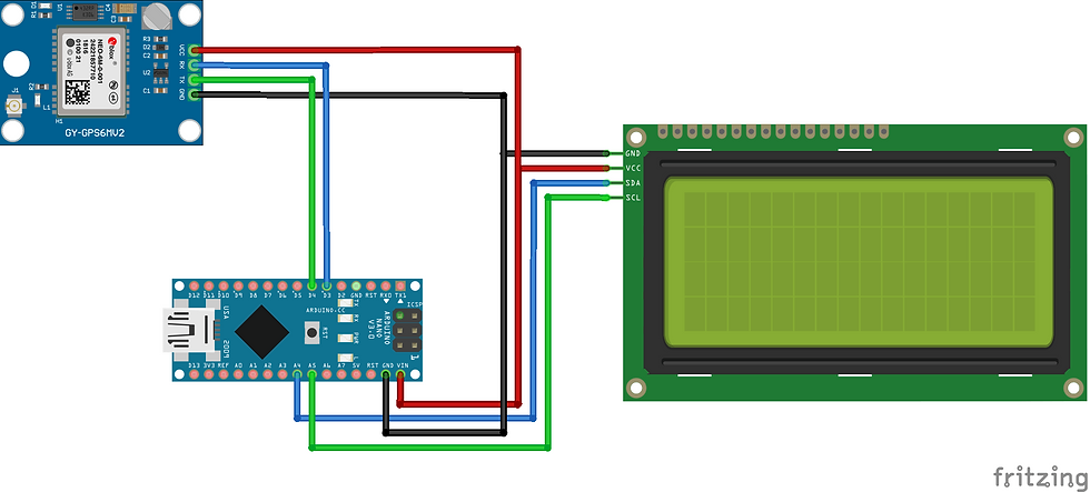
Circuit Diagram
Components Required
Arduino Nano - 1 no
LCD 20x4 with I²C module - 1no
NEO6MV2 GPS Module - 1no
NEO6MV2 GPS

The NEO-6MV2 is a GPS (Global Positioning System) module and is used for navigation. The module simply checks its location on earth and provides output data which is longitude and latitude of its position.It is from a family of stand-alone GPS receivers featuring the high performance u-blox 6 positioning engine. These flexible and cost effective receivers offer numerous connectivity options in a miniature (16 x 12.2 x 2.4 mm) package. The compact architecture, power and memory options make NEO-6 modules ideal for battery operated mobile devices with very strict cost and space constraints. Its Innovative design gives NEO-6MV2 excellent navigation performance even in the most challenging environments.
NEO-6MV2 GPS Module Pin Configuration
The module has four output pins and we will describe the function each pin of them below. The powering of module and communication interface is done through these four pins.
Pin Name Description
VCC Positive power pin
RX UART receive pin
TX UART transmit pin
GND Ground
Features and Electrical Characteristics
Standalone GPS receiver
Anti-jamming technology
UART Interface at the output pins (Can use SPI ,I2C and USB by soldering pins to the chip core)
Under 1 second time-to-first-fix for hot and aided starts
Receiver type: 50 Channels - GPS L1 frequency - SBAS (WAAS, EGNOS, MSAS, GAGAN)
Time-To-First-fix: For Cold Start 32s, For Warm Start 23s, For Hot Start <1s
Maximum navigation update rate: 5Hz
Default baud rate: 9600bps
EEPROM with battery backup
Sensitivity: -160dBm
Supply voltage: 3.6V
Maximum DC current at any output: 10mA
Operation limits: Gravity-4g, Altitude-50000m, Velocity-500m/s
Operating temperature range: -40ºC TO 85°C
Overview of the NEO-6MV2 GPS Module
This module is one of popular GPS modules in the market and is also cheap to buy. The location data provided by it is accurate enough to satisfy most applications. And for it to be included in smart phones and tablets design points out its efficiency. This module is famous among hobbyist and engineers altogether who want to work on applications involving navigation.
How to use the NEO-6MV2 GPS Module
Getting this module to work is very easy. For the application circuit below we have connected the power to board and interfaced the output to the microcontroller UART to get it done.
After circuitry, you need to set the baud rate of the controller matching the module, if it’s not matched you will get error. With baud rate setting done you can read the serial data directly from the module. This data will be longitude and latitude values and the user can play with them as desired.
The raw values provided by the module are cumbersome to read directly and so a simple decimal calculation can be done in programming for getting easy to read values.
Applications
GPS application
Smart phone and tablets
Navigation systems
Drones
Hobby projects
NEO-6MV2 GPS module Datasheet

Installing Library
To install the library navigate to the Sketch > Include Library > Manage Libraries… Wait for Library Manager to download libraries index and update list of installed libraries.
TinyGPSPlus.h : you need to Download and install the GPS library.
LiquidCrystal_I2C.h : you need to Download and install the LiquidCrystal_I2C library.
After installing the required libraries, copy the following code to your Arduino IDE.


Arduino Code
#include <TinyGPSPlus.h>
#include <SoftwareSerial.h>
static const int RXPin = 4, TXPin = 3;
static const uint32_t GPSBaud = 9600;
// The TinyGPSPlus object
TinyGPSPlus gps;
// The serial connection to the GPS device
SoftwareSerial ss(RXPin, TXPin);
#include <LiquidCrystal_I2C.h>
LiquidCrystal_I2C lcd(0x27,20,4); // set the LCD address to 0x27 for a 16 chars and 2 line display
void setup()
{
Serial.begin(115200);
ss.begin(GPSBaud);
lcd.init(); // initialize the lcd
// Print a message to the LCD.
lcd.backlight();
lcd.setCursor(0,0);
lcd.print(" GPS LOCATION ");
lcd.setCursor(0,1);
lcd.print("LATITUDE, LONGITUDE");
lcd.setCursor(0,2);
lcd.print("and GPS CLOCK ");
delay(5000);
lcd.clear();
}
void loop()
{
// This sketch displays information every time a new sentence is correctly encoded.
while (ss.available() > 0)
if (gps.encode(ss.read()))
displayInfo();
if (millis() > 5000 && gps.charsProcessed() < 10)
{
Serial.println(F("No GPS detected: check wiring."));
while(true);
}
}
void displayInfo()
{
Serial.print(F("Location: "));
if (gps.location.isValid())
{
lcd.setCursor(0,0);
lcd.print("Latitude:");
lcd.setCursor(9,0);
lcd.print(gps.location.lat(), 6);
lcd.setCursor(0,1);
lcd.print("Longitude:");
lcd.setCursor(10,1);
lcd.print(gps.location.lng(), 6);
}
else
{
Serial.print(F("INVALID"));
}
Serial.print(F(" Date/Time: "));
if (gps.date.isValid())
{
lcd.setCursor(0,2);
lcd.print("Date:");
lcd.setCursor(6,2);
lcd.print(gps.date.month());
lcd.print("/");
lcd.print(gps.date.day());
lcd.print(F("/"));
lcd.print(gps.date.year());
}
else
{
Serial.print(F("INVALID"));
}
Serial.print(F(" "));
lcd.setCursor(0,3);
lcd.print("Time:");
if (gps.time.isValid())
{
lcd.setCursor(6,3);
if (gps.time.hour() < 10) lcd.print(F("0"));
lcd.print(gps.time.hour());
lcd.print(F(":"));
if (gps.time.minute() < 10) lcd.print(F("0"));
lcd.print(gps.time.minute());
lcd.print(F(":"));
if (gps.time.second() < 10) lcd.print(F("0"));
lcd.print(gps.time.second());
}
else
{
Serial.print(F("INVALID"));
}
Serial.println();
}
Demo Video


Comments