
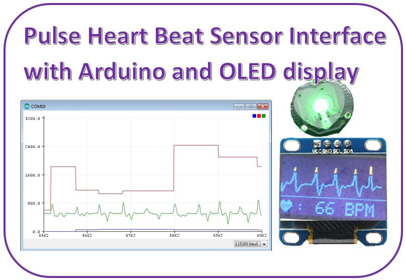
Heart Beat Sensor Interface with Arduino and OLED display
- Ramesh G

- Jun 5, 2021
- 8 min read
In this tutorial, you will learn how to monitor the Heartbeat rate or Heart Beats per minute using the Pulse Sensor, Arduino and OLED display.
This sensor is not for medical use or FDA approved.
Circuit Diagram

Components Required
Arduino Uno - 1 no
Pulse Sensor -1no
OLED 0.96inch I2C - 1 no
LED - 1 no
Resistor - 1no

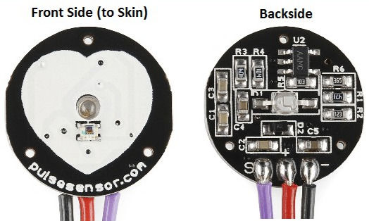
Pulse Sensor
The working of the Pulse/Heart beat sensor is very simple. The sensor has two sides, on one side the LED is placed along with an ambient light sensor and on the other side we have some circuitry. This circuitry is responsible for the amplification and noise cancellation work. The LED on the front side of the sensor is placed over a vein in our human body. This can either be your Finger tip or you ear tips, but it should be placed directly on top of a vein.
Now the LED emits light which will fall on the vein directly. The veins will have blood flow inside them only when the heart is pumping, so if we monitor the flow of blood we can monitor the heart beats as well. If the flow of blood is detected then the ambient light sensor will pick up more light since they will be reflect ted by the blood, this minor change in received light is analysed over time to determine our heart beats.
How to use Pulse sensor
Using the pulse sensor is straight forward, but positioning it in the right way matters. Since all the electronics on the sensor are directly exposed it is also recommended to cover the sensor with hot glue, vinyl tape or other non conductive materials. Also it is not recommended to handle these sensors with wet hands. The flat side of the sensor should be placed on top of the vein and a slight presser should be applied on top of it, normally clips or Velcro tapes are used to attain this pressure.
To use the sensor simply power it using the Vcc and ground pins, the sensor can operate both at +5V or 3.3V system. Once powered connect the Signal pin to the ADC pin of the microcontroller to monitor the change in output voltage. If you are using a development board like Arduino then you can use the readily available code which will make things a lot easier. Refer the datasheet at the bottom of the page for more information on how to interface the sensor with Arduino and how to mount it. The schematics of the sensor, code and processing sketch can be obtained from the Sprakfun product page.

Applications
Sleep Tracking
Anxiety monitoring
Remote patient monitoring/alarm system
Health bands
Advanced gaming consoles
Features
Biometric Pulse Rate or Heart Rate detecting sensor
Plug and Play type sensor
Operating Voltage: +5V or +3.3V
Current Consumption: 4mA
Inbuilt Amplification and Noise cancellation circuit.
Diameter: 0.625”
Thickness: 0.125” Thick
Connect pulse sensor VCC pin to Arduino 5V Pin and GND to GND. Connects its signal pin to Arduino Analog pin A0.
Warning: This sensor is not medical or FDA approved. It is purely intended for hobby projects/demos and should not be use for health critical applications.
0.96″ I2C OLED Display:
This is a 0.96 inch blue OLED display module. The display module can be interfaced with any microcontroller using SPI/IIC protocols. It is having a resolution of 128x64. The package includes display board, display,4 pin male header pre-soldered to board.

OLED (Organic Light-Emitting Diode) is a self light-emitting technology composed of a thin, multi-layered organic film placed between an anode and cathode. In contrast to LCD technology, OLED does not require a backlight. OLED possesses high application potential for virtually all types of displays and is regarded as the ultimate technology for the next generation of flat-panel displays.
Connect the VCC Pin of OLED Display to Arduino 3.3V pin and GND to GND. Connect its SDA & SCK pins to Arduino A4 & A5 pins respectively.
Installing the Arduino Library
LiquidCrystal_I2C.h : you need to Download and install the LiquidCrystal_I2C library.
Download Adafruit_SSD1306_Library , we need to use this library for OLED
Download Adafruit_GFX_Library , we need to use this library for OLED
Follow the next steps to install those libraries.
In your Arduino IDE, to install the libraries go to Sketch > Include Library > Add .ZIP library… and select the library you’ve just downloaded.
After installing the required libraries, copy the following code to your Arduino IDE.
Subscribe and Download code.
Arduino code with OLED:
// Include Library
#include <SPI.h>
#include <Wire.h>
#include <Adafruit_GFX.h>
#include <Adafruit_SSD1306.h>
//
// Configure OLED screen size in pixels
#define SCREEN_WIDTH 128 //--> OLED display width, in pixels
#define SCREEN_HEIGHT 64 //--> OLED display height, in pixels
//
// Declaration for an SSD1306 display connected to I2C (SDA, SCL pins)
#define OLED_RESET -1 // Reset pin # (or -1 if sharing Arduino reset pin)
Adafruit_SSD1306 display(SCREEN_WIDTH, SCREEN_HEIGHT, &Wire, OLED_RESET);
//
// Variable Declarations
unsigned long previousMillisGetHR = 0; //--> will store the last time Millis (to get Heartbeat) was updated.
unsigned long previousMillisResultHR = 0; //--> will store the last time Millis (to get BPM) was updated.
const long intervalGetHR = 20; //--> Interval for reading heart rate (Heartbeat) = 10ms.
const long intervalResultHR = 10000; //--> The reading interval for the result of the Heart Rate calculation is in 10 seconds.
int PulseSensorSignal; //--> Variable to accommodate the signal value from the sensor
const int PulseSensorHRWire = 0; //--> PulseSensor connected to ANALOG PIN 0 (A0 / ADC 0).
const int LED_A1 = A1; //--> LED to detect when the heart is beating. The LED is connected to PIN A1 on the Arduino UNO.
int UpperThreshold = 550; //--> Determine which Signal to "count as a beat", and which to ingore.
int LowerThreshold = 500;
int cntHB = 0; //--> Variable for counting the number of heartbeats.
boolean ThresholdStat = true; //--> Variable for triggers in calculating heartbeats.
int BPMval = 0; //--> Variable to hold the result of heartbeats calculation.
int x=0; //--> Variable axis x graph values to display on OLED
int y=0; //--> Variable axis y graph values to display on OLED
int lastx=0; //--> The graph's last x axis variable value to display on the OLED
int lasty=0; //--> The graph's last y axis variable value to display on the OLED
//
// 'Heart_Icon', 16x16px
// I drew this heart icon at : http://dotmatrixtool.com/
const unsigned char Heart_Icon [] PROGMEM = {
0x00, 0x00, 0x18, 0x30, 0x3c, 0x78, 0x7e, 0xfc, 0xff, 0xfe, 0xff, 0xfe, 0xee, 0xee, 0xd5, 0x56,
0x7b, 0xbc, 0x3f, 0xf8, 0x1f, 0xf0, 0x0f, 0xe0, 0x07, 0xc0, 0x03, 0x80, 0x01, 0x00, 0x00, 0x00
};
//
// void setup
void setup() {
pinMode(LED_A1,OUTPUT); //--> Set LED_3 PIN as Output.
Serial.begin(9600); //--> Set's up Serial Communication at certain speed.
// SSD1306_SWITCHCAPVCC = generate display voltage from 3.3V internally
// Address 0x3C for 128x32 and Address 0x3D for 128x64.
// But on my 128x64 module the 0x3D address doesn't work. What works is the 0x3C address.
// So please try which address works on your module.
if(!display.begin(SSD1306_SWITCHCAPVCC, 0x3C)) {
Serial.println(F("SSD1306 allocation failed"));
for(;;); //--> Don't proceed, loop forever
}
//
// Show initial display buffer contents on the screen
// the library initializes this with an Adafruit splash screen.
display.display();
delay(1000);
//
// Displays BPM value reading information
display.clearDisplay();
display.setTextSize(1);
display.setTextColor(WHITE);
display.setCursor(0, 12); //--> (x position, y position)
display.print(" Please wait");
display.setCursor(0, 22); //--> (x position, y position)
display.print(" 10 seconds");
display.setCursor(0, 32); //--> (x position, y position)
display.print(" to get");
display.setCursor(0, 42); //--> (x position, y position)
display.print(" the Heart Rate value");
display.display();
delay(3000);
//
// Displays the initial display of BPM value
display.clearDisplay(); //--> for Clearing the display
display.drawBitmap(0, 47, Heart_Icon, 16, 16, WHITE); //--> display.drawBitmap(x position, y position, bitmap data, bitmap width, bitmap height, color)
display.drawLine(0, 43, 127, 43, WHITE); //--> drawLine(x1, y1, x2, y2, color)
display.setTextSize(2);
display.setTextColor(WHITE);
display.setCursor(20, 48); //--> (x position, y position)
display.print(": 0 BPM");
display.display();
//
Serial.println();
Serial.println("Please wait 10 seconds to get the BPM Value");
}
//
// void loop
void loop() {
GetHeartRate(); //--> Calling the GetHeartRate() subroutine
}
//
// void GetHeartRate()
// This subroutine is for reading the heart rate and calculating it to get the BPM value.
// To get a BPM value based on a heart rate reading for 10 seconds.
void GetHeartRate() {
// Process of reading heart rate.
unsigned long currentMillisGetHR = millis();
if (currentMillisGetHR - previousMillisGetHR >= intervalGetHR) {
previousMillisGetHR = currentMillisGetHR;
PulseSensorSignal = analogRead(PulseSensorHRWire); //--> holds the incoming raw data. Signal value can range from 0-1024
if (PulseSensorSignal > UpperThreshold && ThresholdStat == true) {
cntHB++;
ThresholdStat = false;
digitalWrite(LED_A1,HIGH);
}
if (PulseSensorSignal < LowerThreshold) {
ThresholdStat = true;
digitalWrite(LED_A1,LOW);
}
DrawGraph(); //--> Calling the DrawGraph() subroutine
}
//
// The process for getting the BPM value.
unsigned long currentMillisResultHR = millis();
if (currentMillisResultHR - previousMillisResultHR >= intervalResultHR) {
previousMillisResultHR = currentMillisResultHR;
BPMval = cntHB * 6; //--> The taken heart rate is for 10 seconds. So to get the BPM value, the total heart rate in 10 seconds x 6.
Serial.print("BPM : ");
Serial.println(BPMval);
display.fillRect(20, 48, 108, 18, BLACK);
display.drawBitmap(0, 47, Heart_Icon, 16, 16, WHITE); //--> display.drawBitmap(x position, y position, bitmap data, bitmap width, bitmap height, color)
display.drawLine(0, 43, 127, 43, WHITE); //--> drawLine(x1, y1, x2, y2, color)
display.setTextSize(2);
display.setTextColor(WHITE);
display.setCursor(20, 48); //--> (x position, y position)
display.print(": ");
display.print(BPMval);
display.print(" BPM");
display.display();
cntHB = 0;
}
//
}
//
// Subroutines for drawing or displaying heart rate graphic signals
void DrawGraph() {
// Condition to reset the graphic display if it fills the width of the OLED screen
if (x > 127) {
display.fillRect(0, 0, 128, 42, BLACK);
x = 0;
lastx = 0;
}
//
// Process signal data to be displayed on OLED in graphic form
int ySignal = PulseSensorSignal;
if (ySignal > 850) ySignal = 850;
if (ySignal < 350) ySignal = 350;
int ySignalMap = map(ySignal, 350, 850, 0, 40); //--> The y-axis used on OLEDs is from 0 to 40
y = 40 - ySignalMap;
//
// Displays the heart rate graph
display.writeLine(lastx,lasty,x,y,WHITE);
display.display();
//
lastx = x;
lasty = y;
x++;
}
Arduino code (Serial Plotter)
Here, We are going to interface a Pulse Sensor with Arduino. The pulse sensor we are going to use is a plug and play heart rate sensor. This sensor is quite easy to use and operate. Place your finger on top of the sensor and it will sense the heartbeat by measuring the change in light from the expansion of capillary blood vessels.


Subscribe and Download code.
#define USE_ARDUINO_INTERRUPTS true
#include <PulseSensorPlayground.h>
/*
The format of our output.
Set this to PROCESSING_VISUALIZER if you're going to run
the Processing Visualizer Sketch.
See https://github.com/WorldFamousElectronics/PulseSensor_Amped_Processing_Visualizer
Set this to SERIAL_PLOTTER if you're going to run
the Arduino IDE's Serial Plotter.
*/
const int OUTPUT_TYPE = SERIAL_PLOTTER;
/*
Pinout:
PULSE_INPUT = Analog Input. Connected to the pulse sensor
purple (signal) wire.
PULSE_BLINK = digital Output. Connected to an LED (and 220 ohm resistor)
that will flash on each detected pulse.
PULSE_FADE = digital Output. PWM pin onnected to an LED (and resistor)
that will smoothly fade with each pulse.
NOTE: PULSE_FADE must be a pin that supports PWM. Do not use
pin 9 or 10, because those pins' PWM interferes with the sample timer.
*/
const int PULSE_INPUT = A0;
const int PULSE_BLINK = 13; // Pin 13 is the on-board LED
const int PULSE_FADE = 5;
const int THRESHOLD = 550; // Adjust this number to avoid noise when idle
/*
All the PulseSensor Playground functions.
*/
PulseSensorPlayground pulseSensor;
void setup() {
/*
Use 115200 baud because that's what the Processing Sketch expects to read,
and because that speed provides about 11 bytes per millisecond.
If we used a slower baud rate, we'd likely write bytes faster than
they can be transmitted, which would mess up the timing
of readSensor() calls, which would make the pulse measurement
not work properly.
*/
Serial.begin(115200);
// Configure the PulseSensor manager.
pulseSensor.analogInput(PULSE_INPUT);
pulseSensor.blinkOnPulse(PULSE_BLINK);
pulseSensor.fadeOnPulse(PULSE_FADE);
pulseSensor.setSerial(Serial);
pulseSensor.setOutputType(OUTPUT_TYPE);
pulseSensor.setThreshold(THRESHOLD);
// Now that everything is ready, start reading the PulseSensor signal.
if (!pulseSensor.begin()) {
/*
PulseSensor initialization failed,
likely because our particular Arduino platform interrupts
aren't supported yet.
If your Sketch hangs here, try PulseSensor_BPM_Alternative.ino,
which doesn't use interrupts.
*/
for(;;) {
// Flash the led to show things didn't work.
digitalWrite(PULSE_BLINK, LOW);
delay(50);
digitalWrite(PULSE_BLINK, HIGH);
delay(50);
}
}
}
void loop() {
/*
Wait a bit.
We don't output every sample, because our baud rate
won't support that much I/O.
*/
delay(20);
// write the latest sample to Serial.
pulseSensor.outputSample();
/*
If a beat has happened since we last checked,
write the per-beat information to Serial.
*/
if (pulseSensor.sawStartOfBeat()) {
pulseSensor.outputBeat();
}
}
After a successful upload, open the Serial Monitor at a baud rate of 115200. Press the “EN/RST” button on the Arduino Uno board and Open Serial plotter and see the result in Serial plotter.


Comments