
NodeMCU Interfaced Knocking Sensor KY-031
- Ramesh G

- Feb 14, 2021
- 3 min read
Updated: Jul 2, 2021
In this project, we will learn about Knock Sensor or Vibration Sensor (sometimes called as Tap Sensor) and how a Knock Sensor works and finally how to Interface a Knock Sensor with NodeMCU 12E and control a Relay.
Components Required
NodeMCU EsP8266 12E
Knock Sensor KY-031

Knock Sensor KY-031
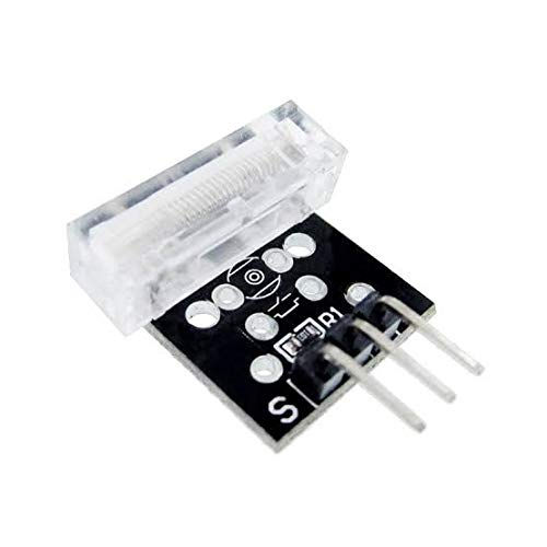
As the name suggests the Knock Sensor Module produces the Digital output on the detection of Knock i.e. vibration stroke. Further, the change in voltage level can be manipulated to produce the desired output and can be used in a variety of applications.
Specifications and Features:
Detect shocks with the spring and send a signal to Controller Board
Operating voltage: 3.3V-5V
Digital output
Relay 1 channel module
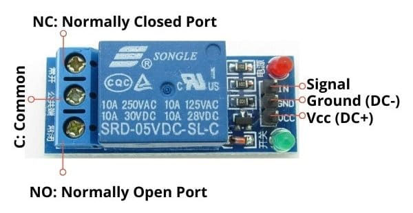
This is 1 Channel 5V Relay Board Module For Arduino PIC AVR DSP ARM. A wide range of microcontrollers such as Arduino, AVR, PIC, ARM and so on can control it. Each one needs 15mA - 20mA driver current and Equipped with high current relay: DC 5V / 10A, AC 250V / 10A Standard interface that can be compatible with microcontroller. Specification and Features : 1 channel relay board Operating Voltage 5V Max Current : 20mA Relay Contact Current Capacity at AC250V: 10A Relay Contact Current Capacity at DC5V: 10A One normally closed contact and one normally open contact Triode drive, increasing relay coil High impedance controller pin Pull-down circuit for avoidance of malfunction Power supply indicator lamp Control indicator lamp Indicator for Relay output status Can Be controlled various appliances & other Equipment With Large current. Standard TTL Level logic controlled (AVR, Arduino, 8051, PIC, ARM) The module is compliant with international safety standards, control and load areas isolation trenches;

Connections with NodeMCU EsP8266 12E:
Sensor signal S Pin are connected to D5 Pin of NodeMCU
Sensor + Pin are connected to Vin Pin of NodeMCU
Sensor - Pin are connected to Gnd Pin of NodeMCU
Relay + Pin are connected to 3.3V Pin of NodeMCU
Relay - Pin are connected to Gnd Pin of NodeMCU
Relay IN Pin are connected to D6 Pin of NodeMCU
Subscribe and Download code.
Arduino Code
const int TapSensorPin = D5; // the pin that the pushbutton is attached to
const int RelayPin = D6; // the pin that the LED is attached to
// Variables will change:
int buttonPushCounter = 0; // counter for the number of button presses
int buttonState = 0; // current state of the button
int lastButtonState = 0; // previous state of the button
int val = 0;
void setup() {
Serial.begin(9600);
pinMode(TapSensorPin, INPUT);
// initialize the LED as an output:
pinMode(RelayPin, OUTPUT);
// initialize serial communication:
}
void loop() {
// read the pushbutton input pin:
val = digitalRead(RelayPin); // read the input pin
digitalWrite(RelayPin, val); // sets the LED to the button's value
buttonState = digitalRead(TapSensorPin);
buttonState = digitalRead(TapSensorPin);
// compare the buttonState to its previous state
if (buttonState != lastButtonState) {
// if the state has changed, increment the counter
if (buttonState == HIGH) {
// if the current state is HIGH then the button
// wend from off to on:
buttonPushCounter++;
Serial.println("ON");
Serial.print("number of button pushes: ");
Serial.println(buttonPushCounter);
Serial.println(val);
delay(100);
}
else {
// if the current state is LOW then the button
Serial.println("OFF");
Serial.println(val);
delay(100);
}
}
// save the current state as the last state,
//for next time through the loop
lastButtonState = buttonState;
if (buttonPushCounter % 5 == 0) { // change 5 to your desired (Knock)knocking counter to Relay on
digitalWrite(RelayPin, HIGH);
} else {
digitalWrite(RelayPin, LOW);
}
}


Comments