
Web Server Based Wireless Video Streaming using ESP32 Camera
- Ramesh G

- Feb 4, 2021
- 3 min read
Updated: Jul 2, 2021
Here to show you how to setup a video streaming web server through Wifi network with low cost budget.
Components Required
FTDI programmer
Jumper wires
ESP32 Camera
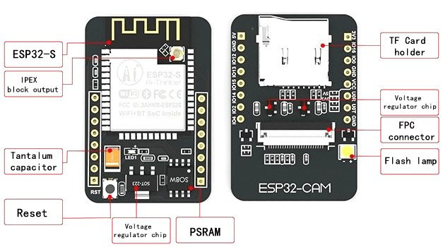
The ESP32 CAM WiFi Module Bluetooth with OV2640 Camera Module 2MP For Face Recognization has a very competitive small-size camera module that can operate independently as a minimum system with a footprint of only 40 x 27 mm; a deep sleep current of up to 6mA and is widely used in various IoT applications.
It is suitable for home smart devices, industrial wireless control, wireless monitoring, and other IoT applications.
This module adopts a DIP package and can be directly inserted into the backplane to realize rapid production of products, providing customers with high-reliability connection mode, which is convenient for application in various IoT hardware terminals.
ESP integrates WiFi, traditional Bluetooth, and BLE Beacon, with 2 high-performance 32-bit LX6 CPUs, 7-stage pipeline architecture. It has the main frequency adjustment range of 80MHz to 240MHz, on-chip sensor, Hall sensor, temperature sensor, etc.
Flash LED off: 180mA @ 5V.
Flash LED on to maximum brightness: 310mA @ 5V.
Deep-sleep: 6mA @ 5V min.
Modem-sleep: 20mA @ 5V min.
Light-sleep: 6.7mA @ 5V min.
Features
Here is a list with the ESP32-CAM features:
The smallest 802.11b/g/n Wi-Fi BT SoC module
Low power 32-bit CPU,can also serve the application processor
Up to 160MHz clock speed, summary computing power up to 600 DMIPS
Built-in 520 KB SRAM, external 4MPSRAM
Supports UART/SPI/I2C/PWM/ADC/DAC
Support OV2640 and OV7670 cameras, built-in flash lamp
Support image WiFI upload
Support TF card
Supports multiple sleep modes
Embedded Lwip and FreeRTOS
Supports STA/AP/STA+AP operation mode
Support Smart Config/AirKiss technology
Support for serial port local and remote firmware upgrades (FOTA)

Specifications :
Wireless Module: ESP32-S WiFi 802.11 b/g/n + Bluetooth 4.2 LE module with PCB antenna, u.FL connector, 32Mbit SPI flash, 4MBit PSRAM.
External Storage: micro SD card slot up to 4GB.
Camera
FPC connector.
Support for OV2640 (sold with a board) or OV7670 cameras.
Image Format: JPEG( OV2640 support only ), BMP, grayscale.
LED flashlight.
Expansion: 16x through-holes with UART, SPI, I2C, PWM.
Misc: Reset button.
Power Supply: 5V via pin header.
Power Consumption.
Flash LED off: 180mA @ 5V.
Flash LED on to maximum brightness: 310mA @ 5V.
Deep-sleep: 6mA @ 5V min.
Modem-sleep: 20mA @ 5V min.
Light-sleep: 6.7mA @ 5V min.
Dimensions (ESP32): 40 x 27 x 12 (LxWxH) mm.
Temperature Range: Operating: -20 ℃ ~ 85 ℃; storage: -40 ℃ ~ 90 ℃ @ < 90%RH.
ESP32-CAM Pinout
The following figure shows the ESP32-CAM pinout (AI-Thinker module).
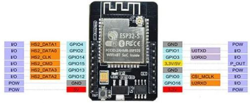
There are three GND pins and two pins for power: either 3.3V or 5V.
GPIO 1 and GPIO 3 are the serial pins. You need these pins to upload code to your board. Additionally, GPIO 0 also plays an important role, since it determines whether the ESP32 is in flashing mode or not. When GPIO 0 is connected to GND, the ESP32 is in flashing mode.
The following pins are internally connected to the microSD card reader:
GPIO 14: CLK
GPIO 15: CMD
GPIO 2: Data 0
GPIO 4: Data 1 (also connected to the on-board LED)
GPIO 12: Data 2
GPIO 13: Data 3
Install the ESP32 add-on
In this example, we use Arduino IDE to program the ESP32-CAM board. So, you need to have Arduino IDE installed as well as the ESP32 add-on
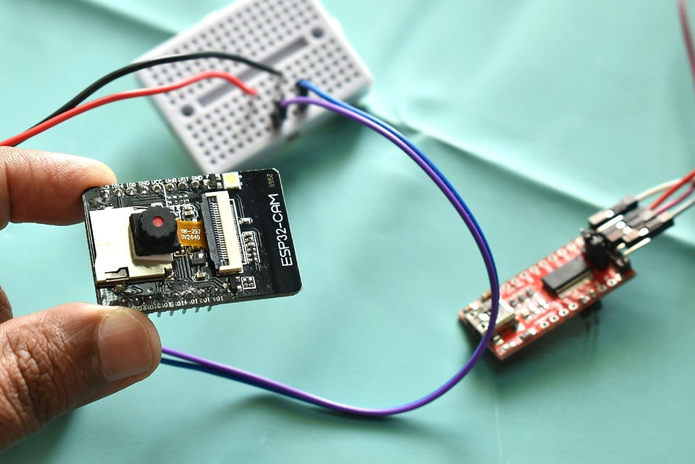
Circuit Diagram:
Connect the ESP32-CAM board to your computer using an FTDI programmer. Many FTDI programmers have a jumper that allows you to select 3.3V or 5V. Make sure the jumper is in the right place to select 5V.

ESP32-CAM FTDI Programmer
GND GND
5VVCC (5V)
U0R TX
U0T RX
GPIO 0 GND
To upload the code, follow the next steps:
Go to Tools > Board and select AI-Thinker ESP32-CAM.
Go to Tools > Port and select the COM port the ESP32 is connected to.
Then, click the upload button to upload the code.
When you start to see these dots on the debugging window as shown below, press the ESP32 CAM on-board RST button.
After a few seconds, the code should be successfully uploaded to your board.

Getting the IP address
After uploading the code, disconnect GPIO 0 from GND.
Open the Serial Monitor at a baud rate of 115200. Press the ESP32-CAM on-board Reset button.
The ESP32 IP address should be printed in the Serial Monitor.

Accessing the Video Streaming Server
Now, you can access your camera streaming server on your local network. Open a browser and type the ESP32-CAM IP address. Press the Start Streaming button to start video streaming.
There are also several camera settings that you can play with to adjust the image settings.
Subscribe and Download code.
Arduino Code: Download


Comments